.png.avif)
generator grounding methods: safety & compliance
- By BISON
Table of Contents
Generator grounding is essential for the safe operation of portable and standby generators powered by internal combustion engines. Proper grounding provides a controlled path for fault current to flow to earth, helping prevent electric shock, equipment damage, and fire hazards. By directing stray electricity away from users and connected devices, grounding reduces the risk of dangerous voltage buildup and system failure.
The appropriate grounding method depends on factors such as the sensitivity of connected equipment, fault current levels, and system voltage. Using an ungrounded generator can lead to short circuits, power surges, and compromised performance.
In this guide, BISON review the fundamentals of generator grounding, explore the different grounding methods and their applications, and outline best practices to ensure safe, efficient, and standards-compliant operation.
What is generator ground?
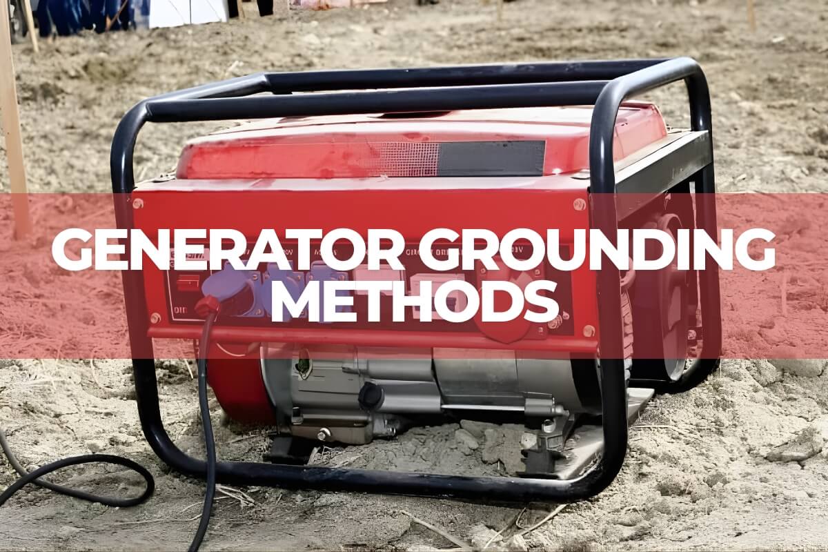
Generator ground refers to the intentional connection between a generator’s electrical system—usually its neutral point—and the earth. This connection creates a low-impedance path for fault current to flow safely into the ground in the event of an earth fault, short circuit, or insulation failure.
In practice, grounding involves connecting the generator’s neutral terminal or frame to the earth using a low-resistance copper grounding wire. A complete grounding system typically includes:
Ground rod: A metal rod driven into the soil to dissipate electrical energy safely into the earth.
Grounding wire: A conductor that connects the generator’s neutral or frame to the ground rod.
Secure connection points: Properly fastened, corrosion-free joints to ensure reliable conductivity.
Together, these components form a grounding system that protects both personnel and equipment while ensuring safe and stable generator operation.
Importance of generator grounding for safety and performance
The main purpose of generator grounding is safety. It provides a direct path for stray or fault current to flow safely into the earth, helping prevent electric shock and protecting anyone operating or maintaining the generator. In the event of a fault, proper grounding ensures that protective devices such as circuit breakers function correctly, allowing fault current to dissipate safely.
Beyond personal safety, grounding protects the generator and connected equipment from voltage surges, short circuits, and insulation failures. This reduces the risk of equipment damage, fire hazards, unexpected downtime, and costly repairs. It also helps maintain stable voltage levels and minimizes electrical noise, which is especially important when powering sensitive electronics or communication systems.
Proper grounding is not only a best practice but also a regulatory requirement. Compliance with standards such as the national electrical code and the international electrotechnical commission ensures that generator systems meet established safety and technical guidelines.
Different methods of generator grounding
Generator grounding is essential for ensuring the safety of personnel and protecting equipment. The appropriate grounding method depends on the generator type, system voltage, installation environment, and operational requirements. Consulting a qualified electrical engineer is recommended when selecting the best solution for a specific application. Below are the main generator grounding methods:
Solid grounding
Solid grounding connects the generator’s neutral point directly to earth through a low-impedance conductor and grounding electrode (such as a ground rod).
This is the most common method in low-voltage and permanent industrial installations. In the event of a ground fault, fault current flows from the faulted phase to the neutral point and then safely to earth.
Advantages:
- Strong fault protection
- Stable system voltage
- Reliable operation of protective devices
- Simple and cost-effective design
Considerations:
- High ground fault currents
- Possible overvoltage during faults
- Requires properly sized grounding conductors and protective devices
Resistance grounding
In resistance grounding, a resistor is installed between the generator’s neutral and ground to limit fault current to a controlled level. This method reduces equipment damage and arc flash risks.
It is commonly divided into two types:
low-resistance grounding (lrg)
A low-resistance grounding resistor (typically 1ω to 10ω) limits fault current to a level high enough to trip protective devices but low enough to prevent serious equipment damage.
Advantages:
- Allows quick fault detection and isolation
- Reduces damage to windings and components
- Common in medium- and high-voltage systems
Disadvantages:
- May produce transient overvoltages
- Requires proper sizing and maintenance
high-resistance grounding (hrg)
High-resistance grounding connects the neutral to earth through a high-value resistor (typically 1 kω to 50 kω). It limits fault current to very low levels and allows continued operation during a single ground fault.
Advantages:
- Minimizes equipment damage
- Reduces arc flash and fire risk
- Allows maintenance teams to locate faults without immediate shutdown
Disadvantages:
- Requires monitoring equipment
- More complex system design
- Hrg is commonly used in industries with continuous processes, such as petrochemical and manufacturing plants.
reactance grounding
Reactance grounding uses a reactor (coil) between the generator neutral and ground. The reactor limits fault current and controls transient overvoltages.
It is typically applied in medium- to high-voltage systems where voltage stability and fault current control are critical.
arc suppression coil grounding
This method uses an arc suppression coil (also known as a petersen coil) connected between neutral and ground. It compensates for capacitive fault currents and reduces arcing during ground faults.
It is mainly used in high-voltage distribution systems to reduce arc damage and improve system stability.
ungrounded (floating neutral) system
In an ungrounded generator, the neutral point is not connected to earth. The system has no direct electrical connection between windings and ground.
Advantages:
- Continued operation during a single ground fault
- Useful for temporary or portable applications
Disadvantages:
- Increased risk of overvoltage
- Ground faults are harder to detect
- Requires insulation monitoring devices
- This method is often used in portable generators or isolated construction sites.
corner grounding (delta systems)
In corner grounding, one phase (corner) of a delta-connected winding is grounded. This provides a system reference point and improves fault detection in specific three-phase delta systems.
It is typically used in specialized industrial motor or heavy equipment applications.
single-point grounding
All equipment grounds are connected to a single grounding point or bus. This method reduces electromagnetic interference (emi) and prevents ground loops.
It is widely used in communication, control, and electronic systems.
multi-point grounding
Multiple grounding points are connected to earth throughout the system. This approach is common in large industrial facilities and high-voltage systems where a single grounding point is impractical.
It reduces overall grounding resistance and provides multiple fault current paths.
common ground with neutral switching
In this method, neutral and ground are connected at a common point (usually the main service panel), with a neutral switching device allowing selective isolation when needed.
Devices such as a ground fault circuit interrupter (gfci) detect current imbalance and disconnect the circuit to prevent electric shock and ground loop formation.
Generator grounding methods: quick comparison
| Grounding Method | Best Application | Core Advantage | Primary Limitation |
| Solid Grounding | Low-voltage, Residential, & Standard Industrial | Simplest & Lowest Cost; Ensures high fault current to trip breakers quickly. | High fault current can cause severe mechanical damage or arc flash. |
| Resistance Grounding | Medium/High-voltage & Critical Manufacturing | Limits Fault Current; HRG allows the system to continue running during a single fault. | Requires additional resistors; higher design and maintenance costs. |
| Reactance Grounding | High-voltage Generators & Utility Systems | Effectively limits fault current while controlling transient overvoltages. | Higher cost; potential for resonance if not matched to system capacitance. |
| Arc Suppression Coil | High-voltage Distribution & Long Cable Runs | Extinguishes Arcs Automatically; compensates for capacitive charging currents. | Complex equipment; requires precise tuning of the coil (Petersen Coil). |
| Ungrounded (Floating) | Mobile Power, Temporary Sites, & Isolated Systems | Continuous Operation; the system doesn’t shut down on the first ground fault. | High risk of transient overvoltages; faults are difficult to locate/detect. |
| Corner Grounding | Specific 3-Phase Delta Industrial Motors | Provides a Stable Reference Point for older Delta-connected systems. | Limited to specific industrial use; rarely seen in modern installations. |
| Single-Point Grounding | Data Centers, Telecom, & Sensitive Electronics | Eliminates Ground Loops; significantly reduces electromagnetic interference (EMI). | Impractical for large systems; if the single link breaks, protection is lost. |
| Multi-Point Grounding | Large Industrial Complexes & High-Voltage Grids | Reduces Overall Resistance; provides multiple paths for fault current. | Can introduce ground loop currents that interfere with sensitive electronics. |
| Neutral Switching | Standby Generators with Transfer Switches (ATS) | Prevents Circulating Currents; ensures GFCI protection works correctly during transfer. | Requires 4-pole switching; wiring logic is more complex and expensive. |
Different methods of generator grounding
Generator grounding is essential for ensuring the safety of personnel and protecting equipment. The appropriate grounding method depends on the generator type, system voltage, installation environment, and operational requirements. Consulting a qualified electrical engineer is recommended when selecting the best solution for a specific application. Below are the main generator grounding methods:
Solid grounding
Solid grounding connects the generator’s neutral point directly to earth through a low-impedance conductor and grounding electrode (such as a ground rod).
This is the most common method in low-voltage and permanent industrial installations. In the event of a ground fault, fault current flows from the faulted phase to the neutral point and then safely to earth.
Advantages:
- Strong fault protection
- Stable system voltage
- Reliable operation of protective devices
- Simple and cost-effective design
Considerations:
- High ground fault currents
- Possible overvoltage during faults
- Requires properly sized grounding conductors and protective devices
Resistance grounding
In resistance grounding, a resistor is installed between the generator’s neutral and ground to limit fault current to a controlled level. This method reduces equipment damage and arc flash risks.
It is commonly divided into two types:
low-resistance grounding (lrg)
A low-resistance grounding resistor (typically 1ω to 10ω) limits fault current to a level high enough to trip protective devices but low enough to prevent serious equipment damage.
Advantages:
- Allows quick fault detection and isolation
- Reduces damage to windings and components
- Common in medium- and high-voltage systems
Disadvantages:
- May produce transient overvoltages
- Requires proper sizing and maintenance
high-resistance grounding (hrg)
High-resistance grounding connects the neutral to earth through a high-value resistor (typically 1 kω to 50 kω). It limits fault current to very low levels and allows continued operation during a single ground fault.
Advantages:
- Minimizes equipment damage
- Reduces arc flash and fire risk
- Allows maintenance teams to locate faults without immediate shutdown
Disadvantages:
- Requires monitoring equipment
- More complex system design
- Hrg is commonly used in industries with continuous processes, such as petrochemical and manufacturing plants.
reactance grounding
Reactance grounding uses a reactor (coil) between the generator neutral and ground. The reactor limits fault current and controls transient overvoltages.
It is typically applied in medium- to high-voltage systems where voltage stability and fault current control are critical.
arc suppression coil grounding
This method uses an arc suppression coil (also known as a petersen coil) connected between neutral and ground. It compensates for capacitive fault currents and reduces arcing during ground faults.
It is mainly used in high-voltage distribution systems to reduce arc damage and improve system stability.
ungrounded (floating neutral) system
In an ungrounded generator, the neutral point is not connected to earth. The system has no direct electrical connection between windings and ground.
Advantages:
- Continued operation during a single ground fault
- Useful for temporary or portable applications
Disadvantages:
- Increased risk of overvoltage
- Ground faults are harder to detect
- Requires insulation monitoring devices
- This method is often used in portable generators or isolated construction sites.
corner grounding (delta systems)
In corner grounding, one phase (corner) of a delta-connected winding is grounded. This provides a system reference point and improves fault detection in specific three-phase delta systems.
It is typically used in specialized industrial motor or heavy equipment applications.
single-point grounding
All equipment grounds are connected to a single grounding point or bus. This method reduces electromagnetic interference (emi) and prevents ground loops.
It is widely used in communication, control, and electronic systems.
multi-point grounding
Multiple grounding points are connected to earth throughout the system. This approach is common in large industrial facilities and high-voltage systems where a single grounding point is impractical.
It reduces overall grounding resistance and provides multiple fault current paths.
common ground with neutral switching
In this method, neutral and ground are connected at a common point (usually the main service panel), with a neutral switching device allowing selective isolation when needed.
Devices such as a ground fault circuit interrupter (gfci) detect current imbalance and disconnect the circuit to prevent electric shock and ground loop formation.
Separately derived vs. Non-separately derived generator systems
In generator installations, systems are classified as either separately derived or non-separately derived, and each has different grounding requirements.
A separately derived system has no direct neutral connection between the generator and the utility source. The generator neutral must be bonded to ground at the generator or transfer switch to establish a reference point and ensure proper fault current return. This setup requires a switching neutral in the transfer switch to keep the generator and utility neutrals isolated.
A non-separately derived system maintains a continuous neutral connection to the utility. No additional neutral-to-ground bond is made at the generator. The system relies on the building’s existing grounding system, and the transfer switch uses a solid (non-switched) neutral.
Proper neutral grounding limits voltage differences between neutral and earth and provides a low-impedance path for fault current. The neutral-to-ground bond location must comply with standards such as the national electrical code and the international electrotechnical commission to avoid shock hazards and equipment damage.
Grounding methods for different types of generators
Grounding requirements vary by generator type and application. Portable, standby, inverter, and industrial generators each have specific grounding considerations to ensure safety, compliance, and stable performance.
Portable generators
Portable generators are typically used for temporary power on job sites or during emergencies.
- If powering equipment through a transfer switch or remote outlets, an external grounding rod is required, with a grounding wire connected from the generator frame to earth.
- If tools or appliances are plugged directly into receptacles mounted on the generator frame, the unit is usually frame-grounded and may not require an external ground rod.
Always verify whether the unit is frame-grounded or system-grounded before operation.
Standby or stationary generators
Standby generators are permanently installed and connected to a building’s electrical system.
- They must be bonded to the building’s grounding electrode system.
- Proper bonding between the generator, transfer switch, and grounding system is required for safe fault current flow.
- Installation must comply with standards such as the national electrical code or the international electrotechnical commission.
Inverter generators
Inverter generators often include internal bonding and voltage regulation.
- Many models do not require additional grounding beyond the frame.
- Some setups—especially when powering sensitive electronics or connecting through transfer equipment—may require external grounding.
- Always follow manufacturer guidelines.
Industrial generators
Industrial generators operate at higher voltages and capacities and require engineered grounding systems.
- Often require multiple grounding electrodes.
- Grounding design depends on voltage level, system size, and installation environment.
Key design considerations and best practices for proper generator grounding
An effective generator grounding system must prioritize safety, equipment protection, and code compliance. Proper conductor sizing, suitable grounding electrodes, and coordinated system design are essential to ensure safe fault current flow and stable operation.
Proper sizing of conductors and electrodes
Grounding conductors must be sized to carry the maximum possible fault current without overheating or failing. The grounding electrode system—such as ground rods, plates, or grids—must provide a low-resistance path to earth so electrical faults can dissipate quickly.
In areas with high soil resistance, longer rods or multiple interconnected rods are often used to improve conductivity and lower overall grounding resistance.
Selection of grounding electrode system
The type of electrode depends on the installation scale and environment:
- Ground rods – common for standard commercial and residential installations.
- Ground plates or grounding grids – preferred in industrial or high-power systems requiring enhanced conductivity.
All connections must be secure, corrosion-resistant, and properly tested to confirm reliable continuity.
Parallel and multiple generator systems
Grounding becomes more complex when generators operate in parallel. Improper bonding can cause circulating currents, voltage imbalance, and equipment damage.
Parallel systems typically require:
- A coordinated neutral grounding scheme
- A common grounding bus or shared electrode system
- Careful neutral-to-ground bonding design
Proper coordination ensures stable fault current paths and balanced system performance.
Compliance and documentation
Grounding design must comply with recognized standards such as the national electrical code and the international electrotechnical commission.
Regular inspection and testing are critical to verify that grounding resistance remains within acceptable limits and that all connections remain intact. Maintaining documentation supports compliance and simplifies future maintenance or system upgrades.
By applying correct sizing, proper electrode selection, coordinated system design, and routine testing, operators can ensure a generator grounding system that delivers safe, stable, and reliable performance throughout its service life.
Common mistakes and troubleshooting in generator grounding
Improper generator grounding can create safety hazards and performance problems.
incorrect neutral-to-ground bonding
Bonding the neutral to ground at the wrong location or at multiple points can cause shock risks, nuisance breaker tripping, and unstable voltage. The neutral-to-ground bond must follow system design and standards such as the national electrical code or the international electrotechnical commission.
inadequate fault current path
Undersized grounding conductors, loose connections, or high-resistance electrodes can prevent protective devices from operating properly during a fault. Conductors must be correctly sized and securely connected to ensure safe fault current flow.
ground loops
Multiple grounding paths can create circulating currents, causing electrical noise, voltage imbalance, and malfunction of sensitive electronics. Proper grounding design, including controlled bonding points or coordinated parallel grounding, helps minimize these issues.
lack of testing and inspection
Grounding systems should be tested regularly using tools such as ground resistance testers, continuity testers, or clamp-on meters. Routine inspections help detect corrosion, loose terminals, or damaged conductors before they become safety risks.
Conclusion
Proper generator grounding is vital for safety, efficient operation, and long-term equipment protection. It provides a safe path for fault currents, reduces the risk of electric shock, prevents damage to sensitive devices, and helps maintain stable voltage levels. The appropriate grounding method depends on the generator type, installation, and application—whether portable, standby, inverter, or industrial.
This guide covered generator grounding fundamentals and methods, including solid, low- and high-resistance, and hybrid grounding. Following electrical codes, using correctly sized conductors and electrodes, and implementing best practices in installation and maintenance are key to reliable operation. Consulting professional generator manufacturers like BISON ensures expert guidance, proper grounding selection, and compliance with global safety standards, enabling safe and dependable generator performance under any conditions.
Need expert grounding advice for your project? Contact BISON engineers